Precision Support Framework
Kinematically-constrained aluminum extrusion framework engineered for sub-pixel registration stability in multi-view reconstruction workflows. The H-frame geometry provides optimal mechanical stiffness while maintaining clear optical access for photometric stereo illumination arrays.
Quick Specifications
Design Evolution & Iterations
The easel design has evolved through multiple iterations to optimize for different photogrammetric requirements and operational constraints. These renderings illustrate the progression from the initial large-format design to a more refined, compact configuration optimized for enhanced mechanical stability.
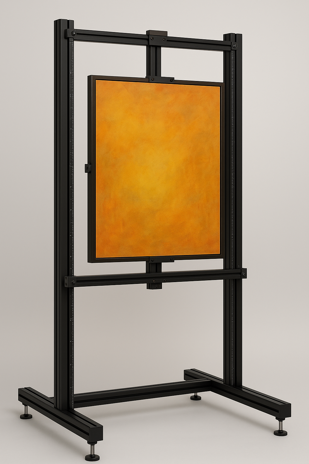
First Iteration - Large Format
- • 2400mm vertical envelope for museum-scale artworks
- • Maximum artwork capacity: 48″ × 60″ paintings
- • Distributed scale reference system for large works
- • Automation mounting points integrated from initial design
Initial implementation prioritizing maximum artwork envelope while establishing the structural foundation for future automation systems.
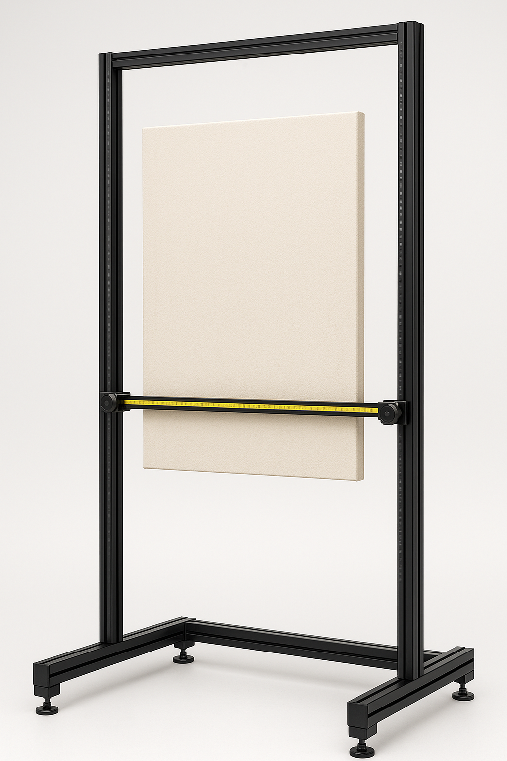
Second Iteration - Optimized Design
- • 1700mm height optimized for most common artwork sizes
- • Enhanced stability through improved center-of-gravity
- • Refined proportions for 32-38″ × 40-48″ typical works
- • Maintains full automation expansion capability
Evolved design balancing practical constraints with mechanical performance, incorporating lessons from initial deployment testing.
Structural Engineering for Photogrammetric Accuracy
Torsional Stiffness Analysis
H-frame geometry provides maximum torsional rigidity per unit mass. The 1400mm base span and parallel 40x80 uprights create a structure with fundamental frequency >15Hz, well above hand tremor frequencies that could induce micro-motion during capture.
Kinematic Constraints
T-slot linear bearing system constrains the artwork carriage to pure vertical translation, eliminating angular degrees of freedom that would compromise multi-view registration. Integrated 300mm precision scales provide sub-millimeter position feedback.
Systematic Design Approach
Modular 8-series T-slot construction enables rapid reconfiguration while maintaining structural integrity. Pre-positioned fastener points accommodate future automation hardware without structural modifications or re-analysis.
MISUMI: Precision Manufacturing Partnership
MISUMI was selected as the primary structural component supplier based on their industry-leading precision manufacturing capabilities and comprehensive T-slot ecosystem. For scientific imaging applications demanding sub-millimeter mechanical accuracy, component selection cannot be arbitrary—every element must contribute to overall system precision.
Manufacturing Excellence
- • ISO 9001:2015 certified precision manufacturing processes
- • ±0.1mm dimensional tolerance on 6063-T5 aluminum extrusions
- • Consistent T-slot geometry ensuring reliable mechanical interfaces
- • Comprehensive material traceability and quality documentation
System Integration Advantages
- • Extensive catalog of precision mounting hardware and accessories
- • Standardized interfaces enabling modular system expansion
- • Engineering support for complex mechanical assemblies
- • Reliable global supply chain ensuring component availability
Technical Specifications
Design Evolution Specifications
- • First iteration: 2400mm H × 1400mm W envelope
- • Second iteration: 1700mm H × 1150-1200mm W optimized
- • Artwork clearance: 300-550mm above floor for illumination access
- • Structural footprint: 110-130mm depth including leveling systems
Material Properties & Surface Treatment
- • MISUMI 6063-T5 aluminum: Optimal strength-to-weight ratio
- • 40×80mm extrusion profile: Maximum section modulus for rigidity
- • Type II anodized finish: 15-25μm thickness, minimal reflectance
- • Precision leveling feet: M10 threads, 10mm adjustment range
Metrology & Calibration Systems
- • MISUMI precision scales: 300mm length, ±0.05mm accuracy
- • Museum-grade contact surfaces: Archival material compatibility
- • Neutral optical background: Maintains photometric accuracy
- • Multi-angle illumination clearance: RTI and photometric stereo ready
Future-Proofed for Linear Stage Integration
A fundamental design principle of this easel system is expandability without structural modification. Rather than retrofitting automation capabilities later—which often compromises precision and requires system redesign—the framework incorporates mounting provisions, clearance envelopes, and pre-positioned fastener points from the initial construction phase.
Design Philosophy: Start Manual, Scale to Automated
The easel functions excellently as a manual positioning system while maintaining the mechanical and electrical infrastructure necessary for future automation upgrades. This approach ensures immediate operational capability while preserving the precision required for eventual robotic integration.
Linear Stage Integration Architecture
- • Closed-side uprights: Mounting rails for linear guides attach without modification
- • Pre-installed T-nuts: Drop-in fastener points eliminate disassembly requirements
- • Carriage beam design: Compatible with belt or lead-screw actuation systems
- • Z-axis encoder integration: Mounting provisions for absolute position feedback
- • Safety interlock points: Emergency stop and collision detection ready
Automation Expansion Capabilities
- • Multi-axis control: Independent X, Y, Z positioning with servo feedback
- • Sensor integration: Laser measurement, environmental monitoring, load sensing
- • Cable management: Sealed T-slot channels route control and power cables
- • Vibration isolation: Dedicated mounts for sensitive instrumentation
- • Expandable I/O: Control system integration points distributed throughout frame
Purpose & Workflow
What the Easel Enables
- • Safe, non-contact support for valuable paintings
- • Square, repeatable alignment for photogrammetry
- • Controlled shadow casting for photometric stereo
- • Quick, tool-less repositioning between takes
Typical Session
- Level frame; set bottom-height stop (~300-500 mm)
- Place painting on felted tray; set rear stops and optional top bar
- Align using the vertical scale plates; capture baseline image
- Run lighting sequence (COB LED at controlled angles)
- Record scale plate segments for calibration in post
Downloads & Media
MISUMI Parts List (Excel)
Living BOM covering both v1 (standard) and v2 (compact) builds: MISUMI extrusion lengths, hardware counts, finishes, calibration accessories, and staging components. This reflects the initial procurement order.
Note: Work in progress — values and part selections may evolve as I refine motion and calibration assemblies.
Build Photos / Renders
FAQ
Why not use adhesive scales or clips on the art?
We avoid any adhesive or edge clips on expensive works. The tray uses archival felt; contact points are padded with neoprene. Scales mount to the uprights, not the artwork.
Can the frame be reduced in size?
Yes. The compact v2 targets 1700 x 1150-1200 mm and is optimized for 32-38″ wide and 40-48″ tall paintings while maintaining ~300-550 mm bottom clearance for raking light.
How do we add linear stages later?
Closed-side uprights accept bolt-on linear rails; the carriage beam can be driven by a belt or lead-screw actuator. We've pre-loaded drop-in T-nuts for no-disassembly installation.